Last Updated on August 28, 2022 by admin
With a well, you’ll require a pressure switch to control the amount of water being pumped into your tank, and this can only be done by installing a pressure switch. There will be a pumping action when there isn’t sufficient water and a stopping action when there is adequate water. As long as you follow the required safety measures, it’s really rather simple to wire a 110-volt pressure switch. This post will go through wiring pressure switches and a 110V well pump pressure switch wiring diagram.
Table Of Contents
About Pressure Switches
Pressure switches are utilized in a wide range of aerospace, military, and manufacturing uses to give equipment with an on or off ability, depending on the movement of pressured fluids. When deciding on a solution for a certain function, understanding how to correctly handle and regulate these switches might be beneficial.
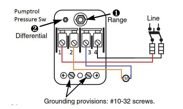
Pressure Switch Diagram
Wiring a pressure switch begins with identifying the essential components. In order to further demonstrate the construction and layout of each part, we’ve provided a wiring schematic.
Wiring 110V Pressure Switch
With a few basic tools, you can easily wire a pressure switch in a matter of minutes. The first step is to cut off the electricity to the pressure switch circuitry. Exposed wires in the pressure switch panel may be accessed by opening the panel.
Connect the input power line from the home to the switch block and secure it using the clamp inside. Wire strippers may be used to remove the cable’s outer jacket and expose the three wires within. Wire strippers may be used to remove 1 inch of insulation from all of the wires.
Applying a wire nut, turn the black wire round the switch’s black wire and secure it. When you’re done twisting, you may remove one of the wire nuts from the switch and remove the other. Attach the cable’s exposed copper ground wire to the green screw on the switch’s inner wall. To keep it in place, use a screwdriver to fasten the screw.
Change the switch’s front panel. Switch on the circuit’s electricity again. Once the pressure switch has been wired, it may be attached to the pressure line by tightening the hex nut connection with a tool. Always use applied force to compress the male pipe firmly.
Know more: 110 Volt Well Pump Wiring Diagram
Testing the Pressure Switch
In order to ensure the quality and safety of your equipment, you must conduct a pressure switch test. As with the pressure switch installation, you’ll need to go through the same stages again.
The pressure switch must be connected to something. Pumps, compressors, and air tanks are the most frequent pressure sources. Set your compressor to expel pressure via the manifolds that are linked with the pressure gauge or gauge and switch, and then turn it off. To verify that the switch is actuated and deactivated, the gauge will display the same pressure level as the switch. Neither oil nor air is being discharged into the environment at this time.
Wire the pressure switch to a lightbox that has an electrical link. The switch will change color from red to green if it is connected to the lightbox and activated. Upon deactivation, the switch will return to its original color of green.
You’re ready to push the switch when everything is set up. After that, open the valve to let oil or air into the system as needed. You’ll know it’s activated when the light goes from red to green, just as in the previous stage. Finally, the pressure gauge must be verified to record the measurement and verify activation.
Finally, shut the valve to prevent the switch from getting any pressure from the water supply. A deadband phase will be crossed and complete deactivation will be achieved when pressure lowers. It’s important to keep an eye on the pressure gauge to make sure it’s not actuated again. The pressure has now dropped to a safe level.
Replacement and Adjustment of Pressure Switch
When replacing a pressure switch, the process is almost identical to the process of putting it in. Remove the pressure switch’s line by unscrewing the pressure switch’s connecting wires. Even though pressure parameters are internally changeable, this does not apply if units are permanent setpoint units. To examine an electrical circuit, unplug the power and use a circuit tester or lightbox that is appropriate.
You may use a screwdriver slot to adjust a pressure switch by loosening the entry cover and turning the adjustment screw. You may then raise or lower the setting by rotating it in either a clockwise or counterclockwise direction. Re-tighten the entry cover, re-connect the electrical circuit, and re-power the device when you’ve completed adjusting the switch.
Conclusion
A Pressure Switch is an essential part of any private well water arrangement. It is the Pressure Switch that controls the flow of water into and out of your house. We hope this post about 110V well pump pressure switch wiring diagram can help you better comprehend it.