Last Updated on July 2, 2023 by admin
There are many types of thermostats on the market these days. If you are looking for a good quality thermostat wiring heat pump then please try to check properly that thermostat before buying. A good quality thermostat wiring you can buy for around less than 50 dollars.
Usually, in the United States, AC power supply is powered by 24V which comes from a 110V/24V power transfer.
If you are not a qualified technician then I would say try to get a qualified technician who can do it properly.
Table Of Contents
Heat pump thermostat wiring Tips
Some Heating, Ventilation, and Air conditioning expert called HVAC experts to use several colors for additional control points. So these diagrams and charts will represent the basic System. That is why we will suggest you read the manufacturer’s instructions. Everything will depend on the manufacturers and designers of the components. How are these components integrated into the system.
Before uninstalling the thermostat try to take a picture of the wires to your cell phone. This way you have good support to wire the thermostat. That picture can help you to make sure that you will join it in the new thermostat correctly.
The post meant the following guide only. Always try to follow manufacturers’ instructions for both thermostats and HVAC Systems. Additionally, this article will help you to solve the problem of thermostat wires properly.
The Basic thermostat wire colours
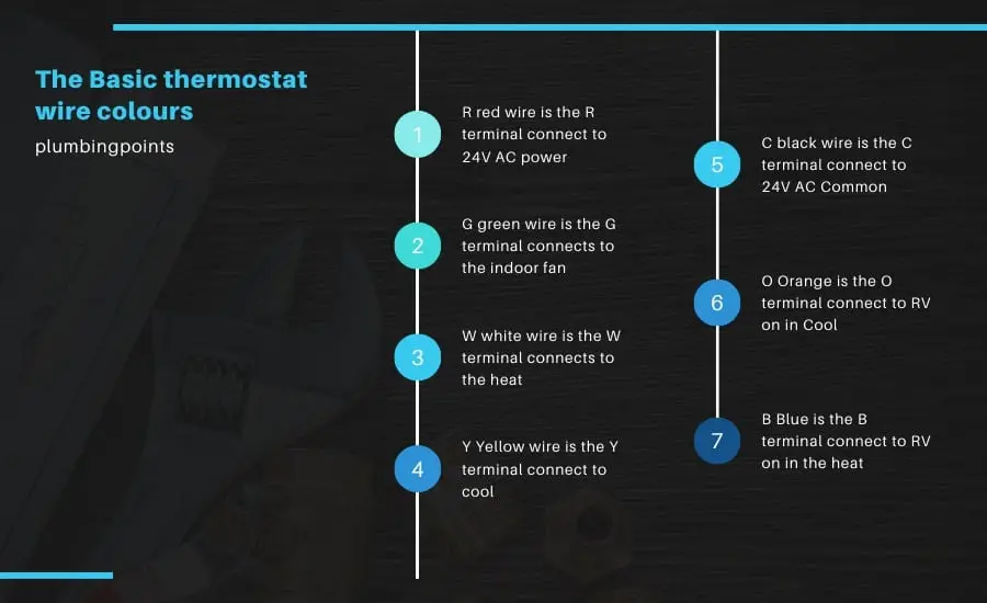
- R red wire is the R terminal connect to 24V AC power
- G green wire is the G terminal connects to the indoor fan
- W white wire is the W terminal connects to the heat
- Y Yellow wire is the Y terminal connect to cool
- C black wire is the C terminal connect to 24V AC Common
- O Orange is the O terminal connect to RV on in Cool
- B Blue is the B terminal connect to RV on in the heat
Thermostat wiring heat pump chart
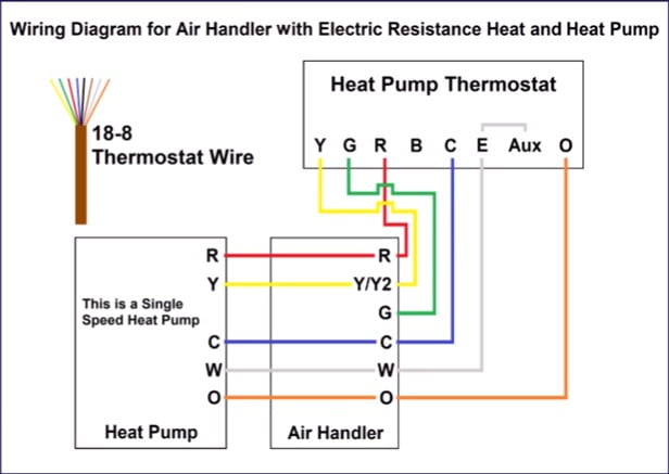
When it comes to the Honeywell thermostat wiring heat pump, you are wiring the heat pump thermostat over to the indoor wire handler you going to typically run 18:8 thermostat wires. You can run an 18:10 thermostat wire which gives you additional wires for a potential outdoor sensor.
The Thermostat color code for the heat pump thermostat over to the indoor air handler. That is why Yellow and G compressors are that green and that’s for the fan. Otherwise Red that’s for 24-volt power, C is blue and that’s common for 24-volt power.
E is typically white and E is emergency heat. Aux, in this case, hampered over to E and Aux mean Auxiliary heat. O is orange and that’s for the reversing valve that leaves two additional wires, one is black, and the second is blown.
You can use it in case there’s a problem in the future. The thermostat wire that you want to run from the air handler to the heat pump is typically going to be 1816 or 18:8 water. In this wiring diagram, you will see that you will use only 5 wires. So if you are an 18-6 wire and you are going to have an additional wire to be safe for the future.
In case, you need to change one of those wires out. If you have an outdoor temperature sensor that ends up finding its way all the way back to the heat pump thermostat you need to run to additional wires from the air handler to the heat pump.
So that means you would end up having to run eighteen eight wire. So powers going to originate at the handler control board and then it’s going to move on from there. So the power goes from the air handler board over to the heat pump thermostat. It connects to the load of the heat pump thermostat.
In order to turn a digital display on and it finds to way back through the common wire over to the air handler control board. You can hardwire that heat pump thermostat or you cannot wire up the C terminal and just use the batteries in the heat pump thermostat also the indoor air handler board. Also, the outdoor heat pump has to do those as well.
If you are going to turn the air conditioner on at the heat pump thermostat or going to send 24 volts over to the G to the Y into the terminals. Then the 24 volts are going to be over on the air handler control board on the Y and G terminals and also the O terminal and then it’s going to continue to make.
It’s way outdoor heat pump on the Y terminal and the reversing valve O terminal. So that’s going to turn on your outdoor heat pump on air conditioning mode. So it’s going to control the compressor.
While you turn on it the heat pump thermostat says at 70 degrees inside the house or inside the building. You turn it up to 71 degrees what’s going to happen is the terminal? It is going to send 24 volts over to the G and also the Y terminals in the heat pump thermostat. The 24 volts is going to make it over to the indoor air handler. The G terminal has 24 volts on. It’s going to tell the blower motor to turn on as well.
You can have the 24 volts on the Y terminal at the air handler then you can also send volts out to the heat pump to turn the compressor on. In this case, you have to reverse the valve with no power heat pump. So, the outdoor pump is running and the indoor air handler is running.
So now say the thermostat is 70 degrees inside the building and you set the thermostat up to about 74 degrees that would end up kicking in the auxiliary heat.
Wiring Heat Pump Thermostats Heat! Terminals, Colors, Functions!
Frequently Asked Questions
How do you wire a single-stage heat pump thermostat?
A single-stage heat pump will have a three-conductor wire running to the fan and compressor.
If you want to control it from more than two separate places, you’ll need a four-conductor wire for the power and three wires for the control, one of which is common.
The Y in the diagram below indicates where current enters the system: through a transformer at its base, flowing out through heavier gauge power cables.
How do I wire a Honeywell thermostat to a heat pump?
Honeywell thermostats usually include a wiring diagram to make installation as easy as possible, but it can typically be wired up like any switch.
It’s also possible to wire in its own fan for cooling down the equipment and adding running costs for potential emergencies. For that, however, the power supply needs to be somehow modulated with a contactor or relay which activates when the outside temperature falls below a certain level (i.e., 15°C/27°F). In this case, wiring in temporary DIN-rail contractors will allow you to lower your thermostat set points during cool periods so that your heat pump has less heating capacity and consumes less power than normal.
What happens if you wire a thermostat wrong?
One of two things typically happens when you wire a thermostat wrong. Either the thermostat is not able to tell that it’s wrong, and keeps heating or cooling the house at the desired temperature, or your device will ignore the signal from your thermostat and disregard what’s turned on.