Last Updated on August 28, 2022 by admin
It might be difficult to get started with wiring zone valves for boiler management, especially if you have never done it before. It’s quite simple to make a mistake if you don’t have the necessary instruction. Low voltage and control wiring aren’t well known to numerous electricians, but it’s a valuable skill to have! The ability to design and install control circuitry sets electricians apart from installers. The Honeywell 4 wire zone valve wiring diagram must be understood as a result.
Table Of Contents
Wiring Honeywell 4 Wire Zone
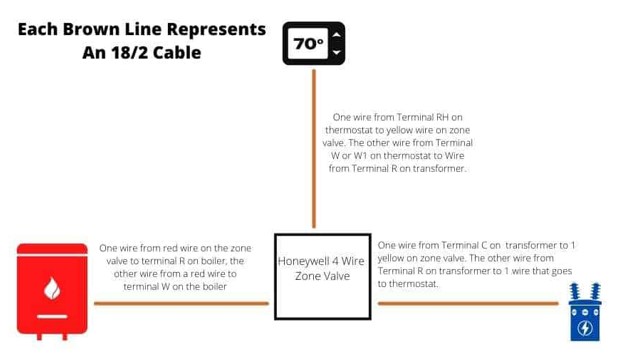
Honeywell 4 wire zone valves need three 18/2 cables for correct wiring. The two yellow wires of the zone valve must be connected using a set of 18/2 cables. When it comes time to wire the zone valve, we will utilize a third 18/2 cable for the red wires. It is recommended that one of the yellow wires be connected to the thermostat. Lastly, connect the 18/2 wires to the 24-volt transformer. Make a series connection by splicing the other wires in between each other. The boiler’s R and W ports should be connected to the zone valve’s red wires.
Wiring Diagram:
To correctly wire, you should first comprehend the Honeywell 4 wire zone valve wiring schematic. Check out this concise wiring schematic for a Honeywell 4-wire zone valve to have a better understanding.
For the sake of clarity, we’ve included a couple of further images of in-field wiring to demonstrate how simple it is.
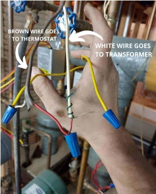
The zone valve’s yellow lines have been connected to two 18/2 cables, as shown. In this particular scenario, the brown wire is destined for the thermostat. The transformer is connected to the white wire.
In this arrangement, the white wire coming from the brown cable is connected to the yellow wire coming from the zone valve. An electrical connection has been established between the brown and white cables’ red wires. At the thermostat, the red wire is connected to Port RH, and the white wire is connected to either Port W or W1 on the other side of the brown cable.
Next, let’s take a glance at the white wire that connects to the 24V transformer. The white wire is connected to terminal C, whereas the red wire is connected to terminal R, both located on the transformer. We have finished working with two of our 18/2 cables at this point. Now is the time to connect the third, which leads to the boiler control panel.
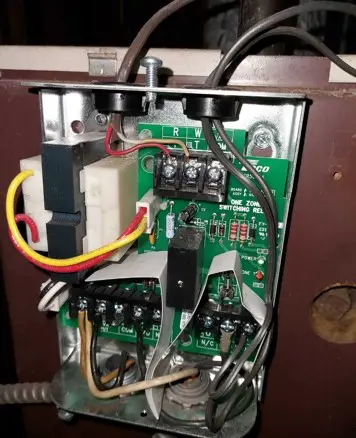
Once the 24 Volt transformer has supplied power to the zone valve, we may connect the zone valve to the thermostat using the wire that was previously disconnected. Finally, the red wires of the 4-wire Honeywell zone valve will be linked to the 18/2 cable, which will then be directed to the boiler’s control panel for completion.
Attach the two wires coming from the 18/2 cable to one of the red lines on the zone valve, and then connect the lines all the way down to the electrical control board for the boiler. These wires will be connected to the R and W ports on the boiler, as noticed in the image that follows.
It truly is that simple. You should be good to go with the wiring for the thermostat, and anytime the thermostat requests heat, it will perform the function of a switch and shut the circuit that runs from one yellow wire to the other endpoint. Because of this, the motor will start, and the zone valve will release. Red wires will provide a signal to a boiler that activates its circulator pump and heats the area when the valve is released. This will bring the temperature up to the desired level.
Overall Operation of Honeywell 4 Wire Zone Valve
A transformer’s 24V power supply is often designated as Terminal RH, thus the red wire leading to the thermostat is connected to that port. The thermostat’s W or W1 terminal has a conventional designation for heating relays, therefore the white wire that connects to it goes there.
Terminals R and W on the boiler are used for the same purpose as the wires on the boiler itself. 24V electricity for heating and heating relays is often referred to by these standard abbreviations. In this scenario, the thermostat serves as a switch since the transformer is always supplying electricity to one of the yellow wires. At low enough temperatures, a switch in the thermostat makes the connection and permits power to flow through. Our yellow wires are carrying 24V electricity when it runs through. We now have a whole circuit in place.
When there is electricity flowing via our yellow wires, a mechanical system in the zone valve opens to allow water to flow through. The red wires on the zone valves carry 24 volts after the zone valve is opened. In order for the boiler to know that the zone valve is accessible and prepared to receive hot water flow, it must be connected to the boiler’s terminals R and W via the red lines on the zone valve.
How to Install & Wire Honeywell 4 Wire Zone Valve
Conclusion
An electrician’s ability to work with low voltage wire is one of his or her most important assets. For starters, it’s a fascinating aspect of the industry. If you’re good enough at it, you can accomplish it on your own. Using your Honeywell 4 wire zone valve wiring diagram knowledge can help you tremendously.